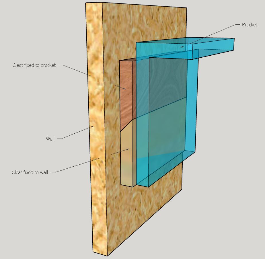
The next part of the build was to mount the panel saws. I looked at the material I had in stock that wouldn't react with steel. I had a large amount of real mahogany and sapele. So I choose to use some mahogany to make the blade holders.
The tablesaw was used with its regular 1/8" blade to cut kerfs. These were spaced 30mm (1.1/4") apart. This spacing seemed fine to be able to extract the saws, prevent the handles from touching and also take up the minimum of space. The kerfs were cut to around 65mm (2.5/8") deep. I cut 9 slots for future tool expansion and then cut the stock to length.
 |
| Then, using a pocket hole jig, mounting holes were drilled on the underneath face. Two screws were enough and attached directly to the lower iroko crossmember. |
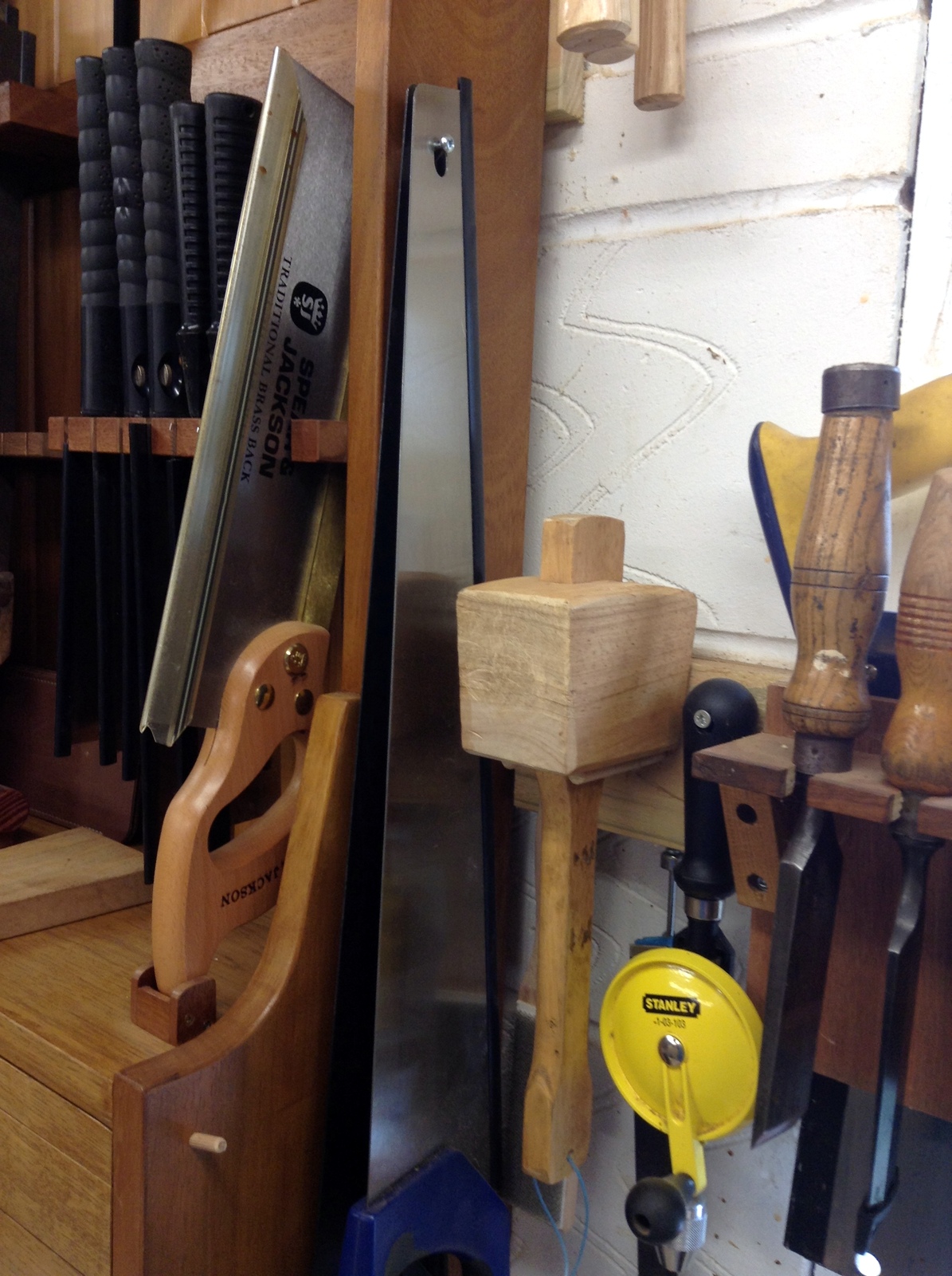
The saw plates on this design are mounted with the teeth facing the operator. For safety I use regular office supply plastic edge binders (3mm for A4 or 1/8" for Letter/Folio) to cover the teeth. This is great if you want to keep tiny fingers from touching the sharp teeth.
 |
| Plastic Edge Binders. Simply slide them onto the teeth (watch your fingers) in multiples cutting the last one to length. It may take a few seconds to remove them but I'm not sure what else I would have done in the time taken to remove them! |
a
 |
| The same tooth guards work on the thickest rip saw to the thinnest gents saw |
The position of the other end (tote end) was worked out empirically. There was some broom handle stock on the shelves so a decision was made to use that.
First of all I carefully inserted all the saws and then pushed the broom stock under the handles. Then the handle stock was lifted and moved it towards the front of the till. This supported the saws at a good angle relative to the vertical and the horns of each handle didn't touch the top surface. Then the gap under the broom handle was measured.
This measurement was used to mill a mahogany support block to width/height. Then a Record 044C plough plane was used to cut a groove down the long axis of the block. A vee groove was then fashioned into the block by using a rabbeting block plane and a small shoulder plane.
The block was then cut into two and mounting holes were drilled through the handle stock.
The block and handle assembly was positioned and screwed into place.
 |
| By then it was found that the saws needed additional support with a lower blade guide too. Another one was quickly made. This wasn't as wide as the top blade guide as the shape of each sawplate was closer to the back wall. The lower blade guide was positioned and screwed into its final place. |
 |
| It was then discovered that the saw handles could slip slightly forward on the handle stock. So another support bar was made and positioned it behind the first one to catch the rear horn of each saw handle. The vee blocks at the rear are slightly shorter in height. |
 |
| Second support bar added at the rear |
The saws were then firmly held in place. I also found if you were using one particular saw and placed it back into the till you could position it so the rear horn caught the front handle support bar. This meant you could always find the saw you were currently using. A little bit of design fluke there but I take full credit for it!
 |
| Design fluke created the ability to place the current saw in such a way that it is quickly available for selection |
The support structure for the smaller saws was made next. There are many pull saws in my collection and again I opted again to have the teeth facing forward hanging down with the handles on top of the support block.
 |
Smaller saw till
Tenon saw supported by a fabricated block of mahogany. |
The table saw was again used to cut narrow kerfs some of which needed to be slightly wider than 1/8". This was to fit the varying types of handle protrusions that Japanese pull saws have. My only western tenon saw needed a very wide kerf to accommodate its brass back.
 |
| The handle of this needed supporting on a captive block so I fabricated one from some mahogany scraps. The block was positioned so the saw leant backwards. |
 |
| A hook was added to hold the veneer roller which was always in the need of a permanent home. |