Sunday 21 October 2018

Jet JWDS-1632-M Review

I had been promising myself a drum sander for quite a while and I had a visit to an Axminster store (Warrington UK) to have a look at what was available.
There were quite a few in my price range:

  • Jet 10-20 Plus Drum Sander £941.30
  • Axminster Trade ST-480 Drum/Brush Sander £1,739.50
  • Powermatic PM2244 Drum Sander £2,269.50
  • Jet JWDS 1632 Drum Sander £1,310.98
However I dismissed the more expensive Axminster and Powermatic sanders as they were much too big for my modest 410 square feet shop. This left the two Jet machines as contenders.

Most of the work I do needs the larger capacity of 32" and some guitars I make are less than 16" width so can be run straight the the sander in one pass. I dismissed the older and smaller Jet 10-20. This left the excellent JWDS 1632 which has been recently redesigned.

The new features are the easy tool-less abrasive retaining clips. This make changing belts an absolute breeze.
The other new features are the conveyor drive motor now pulls the workpiece through the machine, rather than the previous push method. This is supposed to give a much better finish.
Sandsmart™ control continuously monitors the sanding load and automatically reduces the speed of the conveyor if the load becomes too high.
Conveyor bed parallelism is adjusted by turning a simple dial exactly like the much praised Powermatic PM2244. This alone is well worth the outlay to buy this excellent machine.

So I ordered one and added the extra infeed/outfeed tables and the castors. As my shop is relatively small I need to have the ability to move every machine around.


The sander arrived the morning after I ordered it with free shipping from Axminster Tools overnight - astonishing! The shipment comprised 3 boxes on a pallet one of them very heavy.

Stand Assembly

The first thing to do was to unpack the box containing the stand. This is a very substantial folded steel structure which is made from 0.1" (2.54mm) thick heavy gauge steel. This has been powder coated with a white finish. The nuts and coach bolts are made from high tensile steel. All very promising so far.
Stand components

The instructions in the manual are very easy to understand and assembly of the stand on my assembly table took about 30 minutes. The only thing to watch was to make sure the stand has a few components which require holes lining up with each other making up the top of the stand. I used a couple of 3/8" drill shanks to ensure the machine would mount properly. 


Aligning holes using drill shanks
Assembly of the stand was then relatively straight forward.
Stand assembled in sub assemblies
The nuts were only finger tightened at first and then the stand stood on its feet to settle. Then the nuts were fulled tightened with a 12mm socket. I'm not sure what size bolt would be supplied to the USA.

The casters were then installed. It is not necessary to have a thin wrench to hold the fixed portion of the caster shaft as you can get enough grip with your fingers on the circular cup part of the caster.
4 expensive high quality caster came in the box

Tighten the caster with a ring wrench while holding the cupped part of the shaft.
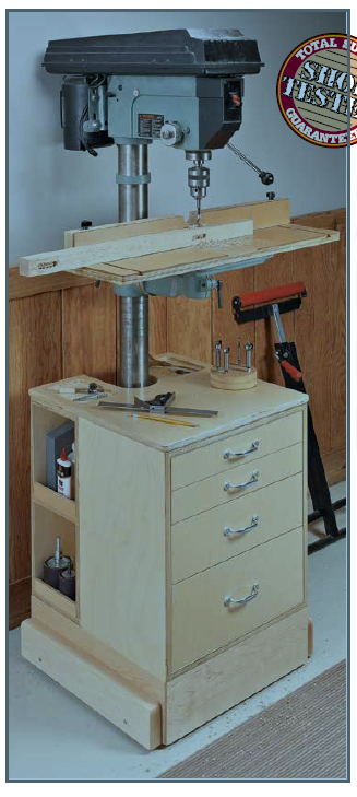
The finished stand

Mounting the machine to the stand.

Cardboard packaging removed from the machine
The plywood sheets are secured to the underside of the machine
with cap head screws.
The machine is very heavy and can't really be lifted by one person so either get a helper or use and engine lifting hoist to lift it out of the box. I got a helper to assist me and we lifted the machine onto the stand temporarily at 90 degrees to its fixed position. This is so the plywood boards can be removed from the bottom of the machine along with the plastic bag the machine is wrapped in.
Then the machine was turned through 90 degrees to its final position. There are 4 holes with welded captive nuts on the underside of the machine which align with the holes in the stand. Then the 4 cap head screws that held the plywood on are inserted, tightened and the assembly is complete.

All that is left to do is mount the winding handle onto the vertical shaft protruding from the top of the machine.
The handle is secured to the shaft with an integral socket grub screw.

 
Finished initial assembly

The handle was then wound to open the mouth and there was a small transportation spacer to discard.

Mounting the infeed/outfeed tables


I had purchased the extra infeed/outfeed tables which effectively double the support area of the machine. These are mounted to the machine using 4 brackets and some more cap head allen screws.
It is essential that the tables are mounted slightly below the level of the conveyor.
I use a 1 metre long steel rule on the conveyor surface. This is gently clamped to the conveyor simply by winding the stationary sanding drum onto the rule.
Then I used a thin steel rule as a spacer to adjust the infeed table (on its slotted holes) to give the desired clearance. This procedure is repeated for the other side of the infeed table. Then the same procedure is repeated on the outfeed table.

Adjusting the outfeed table
 

Control panel

After plugging the power cord into a UK 13 Amp 230 volts socket I tested the machine for power. There are a pair of push buttons one green and the other red which are self explanatory. The green turns on power and the red turns it off.
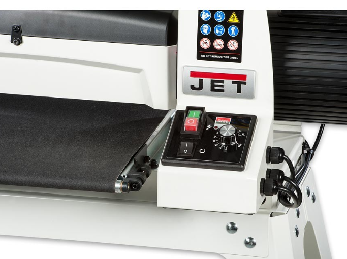
Control panel
The other controls are a rocker switch which turns on the power to the sanding roller.
The remaining rotary control is used to set the speed of the conveyor and is marked in percent 0-100
All worked fine.

UK Specification

  • Abrasive Roll Width 76 mm (3")
  • Dust Extraction Outlet 100 mm (4")
  • Feed Speed 0 to 3 m/min continuously variable (0 to 9.8 feet/min)
  • Model JDS 1632
  • Nett Weight 71 kg (156 pounds)
  • Overall L x W x H 1,007 mm x 508 mm x 1,269 mm (39.6" x 20" x 50")
  • Power 1.1 kW
  • Rating Trade
  • Sanding Drum Diameter 127 mm (5")
  • Sanding Thickness Min\Max 0.8 mm to 75 mm (0.031" to 3")
  • Sanding Width Double Pass 812 mm (32")
  • Sanding Width Single Pass 406 mm (16")
  • Table Size 456 mm x 420 mm (18" x 16.5")
  • Voltage 230 V


Initial testing and adjustments.

The first thing to do was connect a 4" flexible hose connected to my dust extractor to the top mounted 4" port.
I started with a planed 12" length of oak that still had planer ripple marks in. While the machine was stationery I wound the depth handle until the sanding roller just touched the board then I backed the sanding roller off a hair. Then I removed the board and started up the machine. As I hadn't used it before I set the conveyor speed at 50 and switched on the drum motor. 
Then the oak board was placed onto the conveyor and it pulled the board through the machine. All worked ok but as the drum was retracted slightly no sanding took place.
I would the handle down a quarter turn and fed the board through again. Sanding took place and I was surprised just how quiet the machine is. No ear defenders needed. Another quarter turn and another pass resulted in total removal of planing ripple. The machine is supplied with 80 grit paper.

I then turned the board over and did the same on the other side. The finish obtained was suitable for running an orbital sander over.

Sanded board

You can of coarse buy different grits and the quick change spring clips facilitate quick grit changeover.
I had bought a couple of rolls of Abranet 3" x 25metre long abrasive, 1 roll in 80 grit the other in 120 grit. Removal of the original abrasive was super quick.
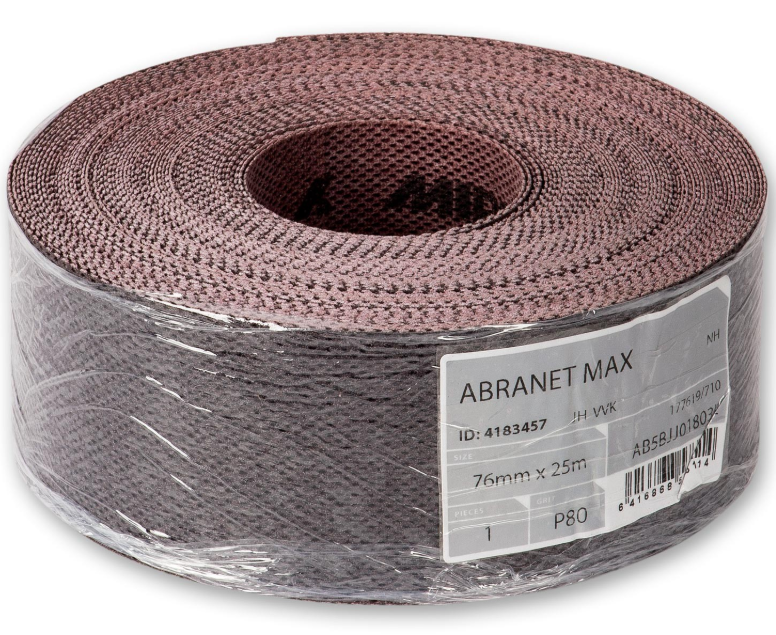
Abranet abrasive belt

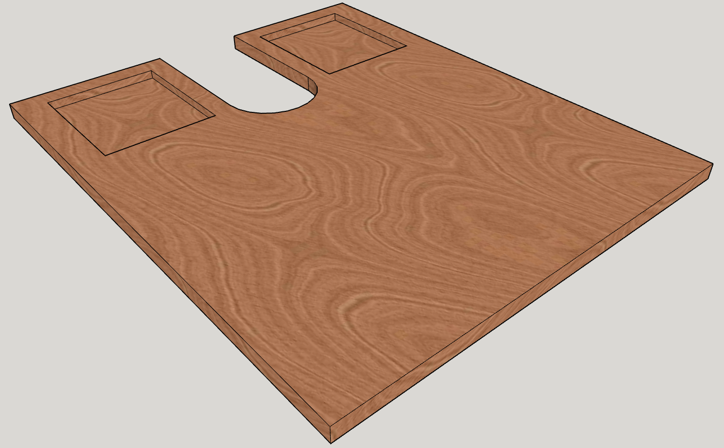
The length of the original Jet supplied abrasive is roughly 2.3 metres which is just less than 8 feet. I decided to make up a template to cut my own abrasive. I used a sheet of 8 x 4 ply and cut off a 5 " width 8 feet long.

I then placed the original abrasive onto the board and held it down with spring clamps. Then using a Sharpie I marked the cut length and the end shapes onto the plywood. Then it was a simple matter of laying the new abrasive onto the plywood and using a box cutter cutting it to length and the end shaping.

Installation onto the machine is really easy using the integral spring clips on the roller winding the abrasive in a tight spiral ensuring that there is no overlap anywhere. The only thing I found was that the abrasive wore out my box cutter very quickly! It is abrasive after all.


Results

I ran through a board wider than the 16" width to test drum parallelism and found that out of the factory is was spot on. There was no discernible ridge when the board was rotated through 180 degrees and run through again on the same thickness setting.

If there was any adjustment needed then there is an adjuster on the open cantilever end and it looks super simple to adjust.

Conveyor parallelism adjuster

Dust collection was excellent and left only a tiny amount of dust on the conveyor. You do need an extractor with decent extraction flow rate though.

Conclusion.

This is an excellent addition to a small workshop and as the machine is trade rated should be able to run long hours every day without issue. The addition of the parallelism adjustment was a deal winner for me. There are no other machines at this price point with this excellent adjuster currently on sale in the UK. The nearest thing is the Powermatic PM2244 which is a considerable larger machine with a hefty price tag.

The machine is extremely well made out of substantial materials and comes with Jet's 3 year warranty. It should last me a long time.

Now I'm off to the shop to play with it.


Monday 3 September 2018

Bringing a table back to life

The newly finished table


A customer brought in a table that had seen better days. It needed its shellac finish refinishing. It was also a little rickety. On closer examination it was literally nailed together! There were no joints to speak of and it needed serious work to make it stable.

I told my customer it would need extensive work but as she liked it and it had no intrinsic value as an antique (laughs) she was happy to see it "remade".

To go about this I dismantled it completely. Not very difficult as the nails came out very easily. The top had been nailed on from the underside and had a dowel protruding from the top of each leg into the underside of the top. Needless to say over a period of years, moving it into central heated houses had resulted in the top splitting down the middle. She wasn't even aware of this as she covered it with a cloth and stacked a computer on it.

The front of the drawer was dovetailed to the sides but the glue had long ago disintegrated. In fact the single wide dovetail was the only thing holding the drawer front onto the sides! The drawer bottom was very thin plywood that protruded from the back. This protrusion had been used as a drawer stop on the inside face of the rear of the carcass! Also it looked as though a bottle of ink had been spilt inside the drawer at some time in its history. Fortunately only the drawer bottom was damaged and a few splashes on the inside of the drawer sides.

Anyway after it was all dismantled I set about correcting it. First of all all the ends of the stiles/stretchers needing squaring up and cutting to identical lengths. Originally they had been cut at odd angles and looks as though they had been chewed to length. It appeared to be made of English oak as it had prominent medullary ray fleck patterns. However it did not smell like oak when cut. I then thought it might be English sycamore which also exhibits ray fleck on quartersawn examples.

Next I made sure the legs were all the same length and squared off both ends. Then all pieces had their shellac removed with a cabinet card scraper. I also used a random orbit sander to 180 grit.

I set about cutting routed slots for floating tenons in the legs/stiles and stretchers. I don't have a Festool Domino but you get the idea. I also made some tenon stock on the router to the correct dimensions and rounded them off to fit the slots.

Dry fit

A dry fit revealed that everything was OK. I cut some notches for the lower shelf. Then the lower shelf was cut to length and width to fit.

Glue up was simple making sure the lower shelf was free to float - no glue. I used clamping squares to make sure everything was ok

Next the ornamental brackets were squared up on the table saw. Again they had previously been chewed to shape! I glued them into place using Titebond regular but only on the long grain faces.

After leaving overnight something had moved and the table rocked slightly. A few passes with a block plane on the two offending legs soon corrected it.

The drawer

Then this left a rail onto which the drawer front would go. As there had been a narrowing of the table caused by me cutting the stretchers square the drawer front was a little too wide. I cut the front to fit the "hole". I then set about cutting the pins slightly deeper. The sides fit in OK and just needed their rear ends cutting square and a rabbet cutting in the trailing edge. A new part of the drawer was the rear panel that I made from some scrap oak. I cut a wider drawer bottom groove in the sides and front to suit some 6mm birch ply I had in stock.
Then I glued the drawer back together and dowelled the rear on. As the dovetails were not very good I also dowelled the drawer front on and left it overnight to cure.

Next day I cut off the protruding dowels and planed the drawer to fit the table. Then a drawer bottom was made and slid into place. This was secured on the back edge with a couple of 2.5mm countersunk head screws.
I just had to glue in a couple of drawer runners and side packers to make the drawer run smoothly and without crabbing.

The top.

I run this over the table saw to cut out the split. The original glue had given way long ago but it was still holding together ... just. I then run both segments through a jointer/planer to get them to a uniform thickness. Then using complimentary jointing method I run the jointer plane over the two mating edges. The top was then glued together with no issues and left overnight to cure.

The next day the top was scraped flush at the seam and the moulding imperfection on the end grain was scraped flush. The results were not perfect but I was not after perfection on this job.

Pre-Finishing

Everything was sanded to 180 grit using a random orbit sander and the mouldings on the lower shelf glued and nailed back into place. I only glued the pieces in about 2" (50mm) at the centre of the end grain and rely on nails on the extremities. This will minimise it popping off when the wood expands/contracts across the grain.

Finishing

My customer liked the original dark wood finish but was happy to let me do whatever I liked to it. So I decided to stay darkish brown. I chose General Finishes Early American waterborne stain as it was fairly close to the original. This needed to be applied in at least 2 coats lightly sanding between with wet and dry 600 grit.

The top coats were General Finishes High Performance Satin as it is another waterborne varnish but is colourless and hard wearing.

Finally the drawer runners were given some Renaissance Wax and the original drawer pulls fixed in place. I made some figure-8 table connectors from some brass sheet and secured the top to the frame. The job was then finished and returned to the customer.


Tuesday 17 April 2018

Making the most of shop storage space

My freestanding shop in the garden was rebuilt from ground up back in 2012. Since then its space usage has inevitably evolved and is in a constant state of flux. Storage space is always at a premium in a small shop such as mine. It is around 410 sq feet in total and this used to be a two stall car garage so you get some idea of its size. I spent many years working out of toolboxes in the original shop but storage was so disorganised I would look for a tool, not find it, end up going out to buy another and then find the original some time later. I would then end up with double or triple of the same item. Something had to be done to storage.
The shop is at the bottom of the garden


The castle overlooks the shop


Wednesday 11 April 2018

Drill Press Upgrade - Part 9 Drawer Construction

4 drawers for the storage unit

The next part of the job was to make 4 drawer boxes from 12mm (1/2") birch ply. I didn't have any birch ply in stock but marine is just as good. I decided to use pinned rabbet joints for strength. This required the drawer fronts to be cut to 12mm less than the drawer width. This compensated for the 6x6mm rabbet to be cut on the front and rear drawer panels.

Typical rabbet joint


The router table was setup to cut 6 x 6 deep slots in the side panels. This setup was also used to cut the slot for the drawer bottom in every drawer panel. Then a 6mm spacer was temporarily affixed to the fence to cut the rabbets. This meant that only one setup of the router table was required.


Rabbet setup. The router table only needs setting once to cut both slots and rabbets using this technique.

The drawers were glued up and left overnight to cure. 6mm dowels were also inserted to lock the panels securely. This isn't as strong as a proper dovetail joint but is good enough for shop furniture.

Tuesday 3 April 2018

Drill Press Upgrade - Part 8 Storage Cabinet Top

This is made from 18mm (3/4") birch plywood and has a cutout to enable it to be fitted around the drill press column.
This was just done using a hole saw and a jigsaw. The edges of the slot were then smoothed using my oscillating spindle sander.

Cabinet Top

The perimeter of the top was edge banded with hardwood.

The underside of the top then had a pair of slots for the sliding doors carefully machined into them.

Underside showing sliding door slots


The next part to be tackled was the pair of routed trays. This is to provide a place to temporarily store items like drill bits to prevent them from falling into a pile of wood shavings never to be seen again!

First of all a simple router template was made in the shape of the tray. Next, using a guide bush, the trays were machined using a handheld router fitted with a cove bit.

The entire top was then sanded and coated with 3 coats of General Finishes Exterior 450. The underside only had 2 coats.

The top was fitted to the cubby/carcase assembly ensuring that the slots in the underside of the top were aligned with the sliding doors.


Tuesday 20 February 2018

Dewalt DW738 - replacing the drive wheel and upper wheel

Unfortunately the rubber tyres on this bandsaw are not capable of being replaced and the wear on the upper wheel after nearly 10 years is considerable. Spare parts are still available (2018) for this machine so I decided to buy a new set of wheels to prolong the life of the bandsaw.

The wheels come as a full assembly complete with bearings, new rubber tyres and are a simply bolt off bolt on arrangement. I also bought a new set of rubbing bearings as the old ones had considerable wear.

The procedure to do this is:

  • Open the access door
  • vacuum any residue from previous operations.
  • Remove the table
  • Remove the blade after loosening the upper wheel tensioner


I also removed the upper rack and pinion assembly complete with bearing assembly. While I was at it I removed the lower bearing assembly.

Slacken the motor

Monday 19 February 2018

Dewalt DW738 - Replacing rear thrust bearings

Over time the rear thrust bearing wear out and can be very easily replaced.
The replacement part is a 608-ZZ-EU (608Z) and has the following characteristics:

  • 22mm outside dia
  • 7mm width
  • 8mm inside diameter
  • double metal shields
  • deep groove ball bearing for thrust and load carrying

Set of new bearings and original bearing shaft

They are very cheap and easily available

To replace the bearings you do have to disassemble various parts of the bandsaw

For the lower bearing


  • Remove the table
  • Loosen the grubscrew holding the lower thrust bearing shaft in place.
  • Gently pull out the shaft. Beware that the grubscrew and nut can fall out so temporarily insert a 10mm drill into the hole and tighten the grubscrew.


For the upper bearing


  • Loosen and remove the nyloc nut and washer holding the rack and pinion adjustment knob in place
  • Remove the rack and pinion assembly complete with mounting shaft
Rack and pinion removed from bandsaw

  • Remove two screws holding the blade guard to the rack and pinion
  • Loosen the grub screw holding the upper bearing shaft in place.
  • Gently pull out the shaft. Beware that the grubscrew and nut can fall out so temporarily insert a 10mm drill into the hole and tighten the grubscrew.

Removing the bearing from the shaft

  • Place the shaft into a suitable 11-12mm inside diameter steel tube and insert both into an engineers vise loosely tighten the vise
  • The bearing should be supported by the tube
  • using a 6mm diameter drill drift or nail punch gently hammer the shaft from the bearing.
  • The shaft will fall into the tube
  • The bearing can be discarded

Replacing the new bearing onto the shaft

  • The new bearing works in both directions so orientation is not a problem
  • insert the stepped head of the shaft into the bearing hole. It will not go in as it is an interference fit.
  • Use a small 6mm socket from a 1/4" square drive socket set
  • Place the narrowest end of the socket onto centre of the bearing. It should be no more than the overall diameter of the inner section of the bearing.
  • Holding the shaft bearing and socket together insert it into the engineers vice and gently tighten the jaws

  • Make sure you have safety glasses on
  • Now gently tighten the jaws ensuring you keep the assembly as square as possible
  • The shaft will go into the bearing until it hits the step on the shaft.


Reassembly

Reassembly for both bearing assemblies is a reverse of respective disassembly

Wednesday 14 February 2018

Drill Press Upgrade - Part 7 Sliding doors and slide ways

The sliding doors are made from some 1/4" birch plywood cut to size. I also glued some thin hardwood finger rails onto each side. This has the benefit of preventing much wood dust falling through the gap and enables fingers to push or pull the doors open or closed.


The slide ways were made on the router from some hardwood scraps.

They are designed so the slide ways simply are glued to the sides.

As can be seen in this view the doors actually protrude beyond the top of the carcass.
This is by design as the door top rail is a slot in the underside of the storage cabinet top
After the slideways were glued the cubby/carcass and slideway fabrication was sanded and finished with General Finishes Exterior 450.

The cabinet top is the next item to be made.


Tuesday 13 February 2018

Drill Press Upgrade - Part 6 Assembly of cubby and carcass

The assembly of the cubbies and carcase is very simple. There is no glue used on this and they are simply held together with wood screws. Clearance holes are drilled into the rear panel of the carcass, the cubby is aligned with the edge of the carcass and clamped into place.
Care is taken to ensure the sliding door slots in the bottom plates are aligned and then they are screwed together.

The same process is carried out on the other side.

If you got your measurements right then the column of the drill press will clear the gap created by the back faces of each cubby.


Monday 12 February 2018

Dewalt DW738 Bandsaw Review

I've had this bandsaw now for nearly 10 years and thought it's about time to review it.
Essentially this is a 13" bandsaw (nominally 12") and has a resaw capacity of 155 mm or 6".
The version I have is a 2 speed saw with the speed changed by moving the drive belt onto different pulleys. When supplied from the factory it is in low speed mode and I didn't move that setting until early on in 2014. Then it was found that it ran much too fast for the type of work I use it for. So I moved it back to the slow speed. It is more trouble than it is worth to change it.
Assembled Dewalt DW738 Bandsaw

There is another saw with a continuously adjustable speed setting and it is designated the DW739. That saw is not reviewed here but probably is similar in specification and operation.

Unlike a lot of good Dewalt equipment it should be a different colour. Like Bosch DIY green against Pro blue. Dewalt DIY stuff needs to be brown instead of corporate professional yellow. It is definitely hobby DIY level but has served me well for the last 10 years.

Reworking the clamp wall

For a number of years I have been building up my clamp wall. The wall is made from concrete blocks and I have simply screwed the shop made clamp racks to it. Over time the wall has got fuller and fuller to which point I needed a change. The white paint on the blocks had become lightly coated with wood dust, as happens in a wood shop, so I had the idea of getting 3 - 4' x 8' sheets of 18mm (3/4") OSB to line the walls.
Organised and fairly tidy

But could do with improvement

A delivery of OSB3 was made a few days ago and I cut them to the right length with my tracksaw. Then it was a simple matter of standing each of them upright and screwing them to the wall using masonry screws. Any load hung on the boards would be partially transferred to the concrete floor and any turning moment would be compensated for by the screws.

A few hours later and the wall was lined with OSB. I then set to work on the wiring. There is an existing double socket for the computer and an existing fused switched outlet for the radiant panel heater. I routed the wiring to suit the required position of the devices.

Wednesday 7 February 2018

Drill Press Upgrade - Part 5 the Cubby Units

The cubby units give the chance for me to store little used items which are still local to the drill press. Occasionally used sanding drums spring to mind for usage here.

The cubbies themselves again are open boxes made from 18mm (3/4") birch plywood. They are made in a similar way to the storage carcass using glued and screwed construction. Nothing major or difficult to do here.

2 storage cubbies like this are required
I put a shelf in the centre of the vertical span and the back is made from 12mm (1/2") birch ply.
There are also glued in shelf rails to minimise things falling out should a door be open and you decide to move the storage unit.

Cubby without its shelf - this will be glued in after assembly to the storage unit


Monday 5 February 2018

Drill Press Upgrade - Part 4 the Storage Unit Carcase

The carcase is a very simply construction and is basically and open box. This is entirely made from birch plywood 18mm (3/4" nominal) thickness.
Carcase design
Cutting the plywood is best performed with a tracksaw but can be done with a conventional circular saw/edge guide or, if you are feeling strong, the tablesaw.
Since getting my Bosch tracksaw I have long given up on cutting sheet goods with a tablesaw or any other tool for that matter. The tracksaw is the perfect tool for the job and you don't end up with a hernia or a chiropractors bill!

Each of the components was cut to size. I then used the router table with a rabbeting bit to cut the various rebates (rabbets US). My European tablesaw does not have an arbor that will take a dado stack but I know a few of my North American friends use them.

Once the rebates were cut the rear and side plates were drilled with a 75mm (3") pitch of pocket holes around the perimeter. As already mentioned the addition of mechanical fasteners (pocket screws) in addition to glue and rabbets makes for an immensely strong joint.
The components were glued and screwed together.


Friday 26 January 2018

Drill Press Upgrade - Part 3 the Storage Unit mobile base

The next part of the project is the mobile base onto which the storage unit is mounted. The mobile base itself is designed to nest around the drill press mobile base. There is also a notch in its top plate to allow the unit to fit around the column of the drill press.

My design of wheel axle is slightly different than the WoodSmith plans consequently making the storage unit slightly wider. That in itself is not a problem but an opportunity for increased storage space! My shop can cope admirably with a storage unit a couple of inches wider than the plans.
View from rear of drill press showing nesting of  both mobile bases


I measured the resultant drill press mobile base width and changed my Sketchup drawings accordingly.

Exploded view of the storage unit mobile base


Again construction of this is utilising birch plywood and construction lumber. The sides and front of the base are rabbeted and are glued/screwed to the top. I decided to use pocket hole construction to augment the glue and rabbets.

The wheel blocking again was made from construction lumber but this time a cover plate was added. This covers the wheels but allow a full axle pin to be inserted from the outside and through into the side plate. This has a pair of washers, one either side of the wheel faces to provide a bearing face. Sufficient clearance is given by carefully measuring the washer and wheel assembly combined thickness and planing the blocking to that thickness + a few thousandths of an inch.

The axle holes were drilled with an drill guide of the correct diameter. This ensured that the holes were exactly drilled at rigt angles to the face of the boards. The holes were drilled blind into the plywood to about 13mm (1/2") deep. Then this hole had a 4mm through hole drilled into it. This ensures that the axle pin does not push through but still can be extracted, with a small diameter pin punch, for maintenance.

Then the top plate is notched out to suit the column of the drill press.

The fabrication was then rounded over with a router round over bit where necessary. Then it was finished with General Finishes Exterior 450.

The axle pin is held in place with a grub screw bearing onto a filed flat on the axle.


Again the resultant mobile base is strong, stable and the ideal platform for the carcase.


Monday 22 January 2018

Drill Press Upgrade - Part 2 the drill press mobile base

This is a very simple platform constructed from birch plywood and some softwood I had lying on the shop shelves.
The distance between the side panels is made to suit your particular drill press base.

The side panels are glued and conventionally screwed to the plywood base. It is important to also use screws when gluing anything that is taking weight to plywood. The plywood face veneers are only held on with glue and are thin. So the glue between the plywood layers itself probably won't fail but the thin wood veneer may shear away.

The axles I used were simply M8 (3/8") coachbolts. Their square ends are on the inner faces of the side boards.
There is also a large penny washer and nut holding the bolt securely. The washer and nut are set into a counter bored hole on the outside of the side boards.
There is a further washer, the wheel itself, another washer and a Nyloc locking nut holding each wheel onto the axle. When adjusting the Nyloc nut it is easy to give sufficient end float clearance to allow the wheels to freely rotate without slop.


The next part is the wheel blocking which also carries the jacking screws. This again is made from softwood. I put metal screw inserts into the underside to carry the jacking screws. The blocking is cut to suit the radius of the wheels and each one is glued and screwed to the mobile base fabrication.

The jack screws themselves have knobs fixed to them to allow you to jack easily from above. I fixed the knobs to the screws with locknuts. The blocking needs clearance to allow the knobs to screw down and operate. This picture shows my solution.

Then all edges are rounded off with a router roundover bit. This last part is not essential but makes for a neat appearance. The whole fabrication is sanded and finished with General Finishes Exterior 450.

I disassembled the drill press and placed the base onto the mobile base. I then drilled for metal screw inserts and used suitable bolts/washers to secure it to the mobile base. 
At the time of taking this photograph I didn't have the knobs fitted to the jacking screws

The result is a very firm linear mobile base with a low centre of gravity.


Monday 15 January 2018

Drill Press Upgrade - Part 1 Design Process

For years I have persevered with my floor mounted drill press. I had fastened this to the concrete floor in the shop with anchor bolts but the position of it wasn't ideal. Obviously a home workshop is in a constant state of flux and is constantly evolving so my initial thoughts on where it should be sited have now changed. When you find a need for a change to your particular workflow if there is something bolted down it can limit your plans.
This project is intended to give me more flexibility in the location of the drill press in my shop.
Also I want to have extra drawer storage space so I designed this into the project.

The main criteria was:

  • Ability to move the drill press
  • A stabilized base
  • Storage space local to the drill press


So I looked around for potential plans and found one from Woodsmith.
It seemed to fill all my requirements so I adapted the plans to suit my particular drill press.


The thing I liked about the plans were the mobile base with a low centre of gravity and a nesting storage unit. This is also on wheels and can be pulled out so allowing the drill press full height to be used if necessary. I don't have a requirement to wheel the press all around the shop as if on a shopping cart with rotating castors so the fixed axis wheels are fine for my needs.
Also I conventional metal mobile base would not suit my particular requirements so was discounted completely.

So here is my Sketchup representation of the entire mobile base/storage unit shown as exploded and nested.

This shows the storage unit nesting around the mobile base.
I used a 3D model of a Delta drill Press that I found on the
Skecthup 3D Warehouse. It was close enough dimensionally to my
drillpress.

This shows how the storage unit can be pulled out on
its integral wheels (hidden by the side plate)
should the need to use the full capacity of the drill press be required.
The drill press mobile base also has screw jacks to further stabilise the
whole of the floor stand.

This is an exploded view of the storage unit.
4 drawers and 4 storage cubbies give further storage space
to a crowded small shop.

I decided to make the entire unit from birch plywood and some construction timber. The edges of the drawer fronts and storage unit top were to be edge banded with hardwood.

Full extension 10" (250mm) stainless steel slideways for the drawers, 8 x 3" diameter no mar wheels and 4 jacking screws with non slip pads make up the hardware for the entire project.

Also as much as possible glued and pocket screws construction is used. Pocket screws can be immensely strong, especially for shop furniture, and I believe get a bad press. I have made loads of sheet good based projects with pockets screws and find them very strong.  Maybe the advent of the Festool Domino has created this perception, I don't want to start a debate on this (you are free to start another thread if you desire) but I don't currently have one so pocket screws it is.

Wednesday 10 January 2018

2018 has arrived and no woodworking - yet

It is a cold January 2018 day today. The car was frozen up and I opened the shop for the first time since before Christmas and put the heating on. Nothing had rusted so the application of CRC 3-36 periodically throughout the year had worked its benefits.

CRC 3-36 Corrosion Protection

I have a few jobs lined up to do this year at least until spring. My nephew and niece-in-law are having a new baby in a couple of weeks and a request has been made to build a toy chest similar to one I made a few years back. I have a stock of oak and need to buy some birch plywood and some special hinges. The hinges prevent tiny fingers being trapped as they stop the lid from falling too quickly.

Toy Chest made in January 2015


I also have a request from a customer to build a metronome. The customer will supply the mechanism and gave me some wood, I believe it is utile, in barter for making the case.

Further purchases planned for the year are a new bandsaw (probably an 18" for resaws) and a Domino DF500. I have to get these in this year as Brexit may bring price hikes.

Festool Domino DF500
There is also a 5 string fretless bass that I am part way through to finish off.

Drilling the hole for the bridge earthing/grounding strap

Applying CA glue to the fretboard. Mahogany markers have been inlayed
as fret positions.

There are a few other jobs that I also have to start.